System Architecture
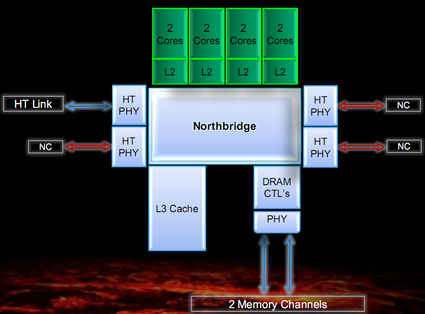
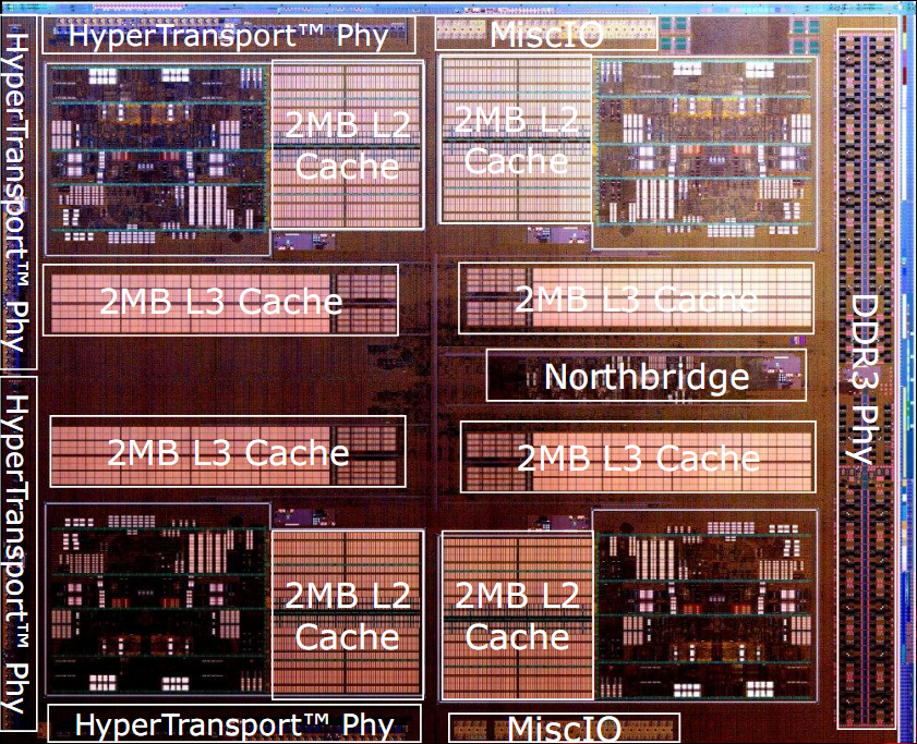
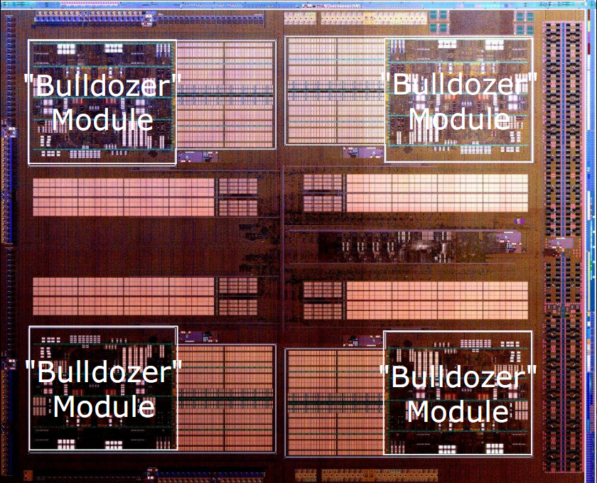
In the figure are shown a simplified block diagram and two photos of Bulldozer dices, with outlined the various components of the architecture.
The first thing to note is that the minimum unit of processing is the so-called module, which implements two Bulldozer class core.
The chip architecture includes four modules, each consisting of two cores and 2MB of shared L2 cache, a North Bridge that manages the interconnection between all the elements of the chip, 8MB of shared L3 cache, a dual-channel DDR3 memory controller and four HyperTransport controller, of which only one active in the CPU desktop class.
The ultimate goal of AMD's designers was to maximize the performance-per-watt, taking into account also the occupied area. This was achieved in various ways. From an analysis of the literature is emerged that there is an optimal processor pipeline complexity to get the best performance per watt ratio.
Simple pipeline and with a large number of stages allow you to have high clock, but low IPC (instructions per clock). Consumption explodes with clock increase and then you can not increase too much this parameter, reaching an impassable limit on performance.
Complex pipeline, with few stages are slower, but have high IPC, balancing the lower clock. Having a large number of transistors, occupy more chip area and consume more energy in leakage (leakage currents), due to the large number of transistors. This also translates into an additional limitation to the maximum achievable clock.
The optimal condition is halfway between these two extremes and was established by several theoretical studies in the literature. An index of the pipeline complexity is the FO4, which indicates how much is the normalized delay of one pipeline stage. The higher this number, the more complex (and slow) is the stage of the pipeline, and hopefully less pipeline stages are needed to implement a given architecture.
It has been shown that a 17-FO4 is the optimum for a CPU built on modern production processes. This value is that used for the Bulldozer pipeline. By way of comparison, the K10 has a FO4 of about 22, while the Sandy Bridge has about 24 and that of a Pentium 4, about 13. For what said before, it's clear that K10 and Sandy Bridge are complex pipeline architectures and low clock while the Pentium 4 is a simple pipeline architecture with high clock.
Given the complexity of the optimal pipeline now the problem is to implement the CPU with a minimum number of transistors.
One of the things that was done is the sharing of all underutilized units. This is why the birth of the module.
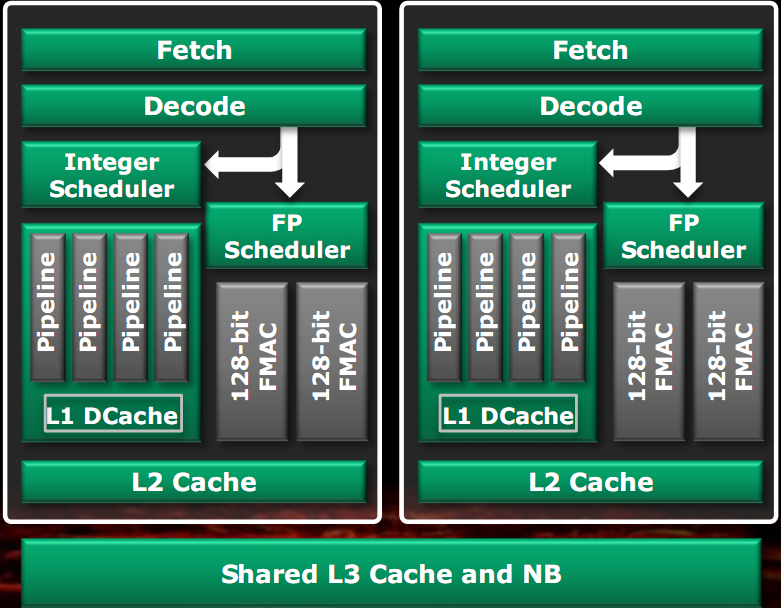
In the left figure we can see the classic implementation of a dual core CPU, with duplication of most of the components.
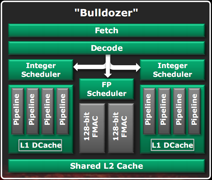
In the right figure is shown a block diagram of a Bulldozer module.
Units that are not used in full for most of the time were shared between two cores, so you may also make them more powerful than the case of separate units, because now the transistors budget is divided between two core and then you can use more for a single unit.
As shown in the figure, the shared units are the fetch unit, the decode unit, the floating point unit and the L2 cache. The L1 data caches and integer units have been separated since it was established that they are the most commonly used units of a core. This approach allows two threads to run at an average speed of 80% compared to the case of separate cores in an area of only 12% more than a single core (not counting the L3 cache, the North bridge controller and the RAM).
Lowering the number of transistors, lowers the leakage and thus allows higher clock at the same TDP. But to have even higher clock we must have a very effective energy saving.
The strategies implemented in Bulldozers are: the extensive clock gating of logic networks throughout the die, i.e. off the clock for the units not used in a given time; extensive power gating logic circuits, i.e. off the power supply for units not used at any given moment; C6 off state implementation for the modules or the entire package, with rings around the drive transistors; P-state for energy savings or turbo-core, to have at any time the optimal consumption in function of load, a feature allowed by the APM module (advanced power management), which measures instantaneously the consumption of the chip and determines the optimal P-state; the energy savings of the RAM modules and finally the C1E power state, in which an idle core consumes as little as possible without being turned off completely.
Last implemented feature in Bulldozer is Turbo Core.

The turbo core uses the APM unit to determine how long the CPU can be in the best possible state of turbo without exceeding the maximum consumption limit. When all the cores are used, there is almost always some units not used in the chip. The APM unit calculates the TDP budget and the turbo core unit, using a dithering algorithm, calculates how much time the CPU can be in a state of turbo without exceeding the TDP. If you have used half or less of the core, the usable turbo state provides even higher clock.
We come now to a list of the main features of the various units of a Bulldozer module.